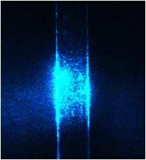
The Flow Cytometer Maker lab is intended to be assembled by students under the guidance of an instructor. It starts with an empty carbon fiber breadboard, and the various components of the cytometer (laser, optics, flow cell, etc.) are added in sequence. The instrument is then aligned and connected to its electronics an computer. Fluorescent microspheres are usually used as analysis material, although it can also run cells. By running microspheres, we can visualize the stream on the camera.
The system is constantly being improved. Feedback is very welcome!
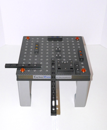
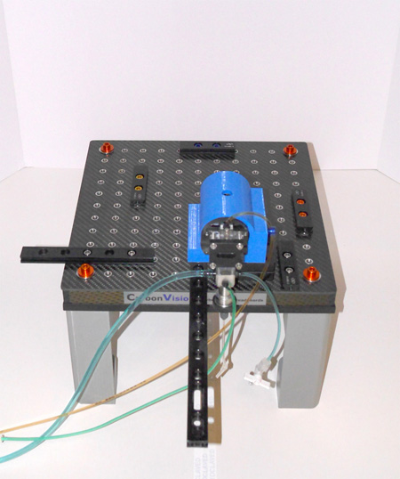
Here is the breadboard. It is supported on 3D printed ABS plastic legs, and already has some optical rails mounted on it to facilitate assembly of the other components.
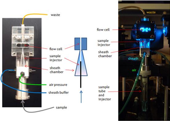
First, we mount the flow cell and light collection optics. These are mounted in a single unit that clamps to the breadboard. The flow cell and optics are both from a BD FACScan flow cytometer, and are coupled together using an optical gel. The fluidic and air lines for the flow cell are already attached.
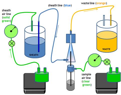
The air lines of the flow cell are green, the sheath buffer feed line is blue, and the waste line is orange.
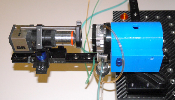
Next, we mount the stream camera on the long camera arm protruding from the front of the breadboard. This CCD camera is equipped with a 5X widefield objective to visualize the flow cell capillary channel and stream. The camera has a 488 nm notch filter to exclude laser light and only visualize the stream running fluorescent microspheres.
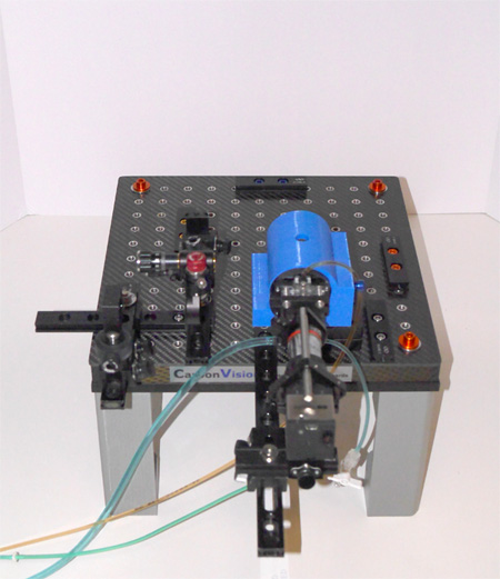
We now mount the 488 nm laser. This small DPSS unit manufacturered by Vortran Laser is mounted on a heat sink, and used micro optical rail mounts (like most components on the system) to attach to the breadboard.
The laser focusing lens and steering prism are then attached. The lens is a 100 mm focal length achromat taken from a BD Biosciences FACSVantage, and focuses the laser beam on the flow cell and the stream. The steering prism is a flat glass prism that allows the laser beam to be translated up or down and left or right by adjusting the angle of the prism. The prism has both course adjustment (by moving the mount) and fine adjustment, using fine actuators to adjust the position of the beam.
The laser is then turned on, and the camera activated and focused onto the flow cell with the 488 nm notch filter removed. Even if the laser light is not directly hitting the flow cell capillary, the stray light should be enough to visualize the capillary. The laser beam alignment can then be adjusted until the laser is approximately hitting the flow cell capillary.
The walls of the flow cell capillary and the beam are both visible on the camera.
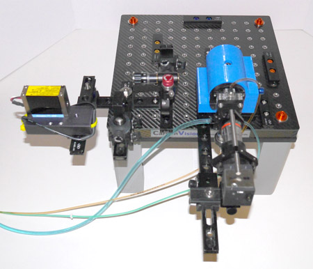
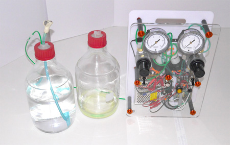
The air pump module is then set up. This unit contains two air pump, two air switches to turn on and off the air pressure, two regulators, and two pressure gauges. The left hand components control pressure for the the sheath air, the right hand components for the sample air.
The air line tubing is colored green, the sheath line is colored blue and the waste line is colored orange. The sheath air line use opaque green tubing, the sample air lines use clear green tubing. Two bottles with caps equipped with two Luer ports are used as sheath and waste containers. The sheath container must be air-tight.
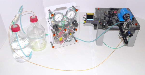
To connect the air and fluidics:
(1) Connect the blue sheath line from the flow cell to the sheath bottle.
(2) Connect the clear green sample air line from the flow cell to the sample air port on the fluidics unit
(3) Connect the orange waste line from the flow cell to the waste bottle.
(4) Connect the opaque green air line from the sheath bottle to the air pump unit.
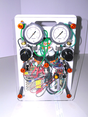
The air pumps, pressure gauges regulators and pneumatic switches are visible on the front of the console. Power supplies for the air pumps and lasers are also visible.