Continued assembly instructions for the Make Your Own Cytometer.
Click here to go to the previous page, or here to go back to the main page.
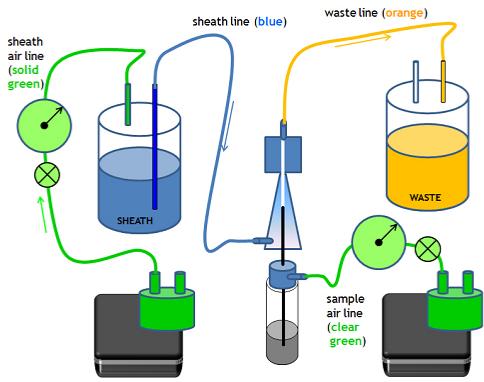
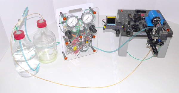
Schematic for the instrument air and sheath lines.
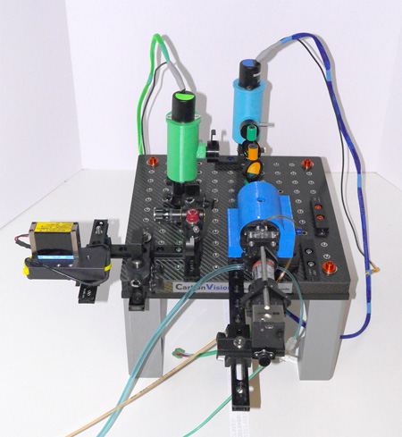
Here is what the system looks like after connecting the air pump unit, the sheath and waste lines and the sheath and waste bottles.
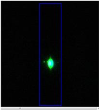
Next, turn on the pumps and pressurize both the sheath and waste lines. Mount a sample tube containing polyscience 10 micron YG microspheres on the flow cell SIP tube. Adjust the sheath pressure to approximately 2 psi, and the sample pressure to about 3 psi. Insert the 488 nm notch filte into the camera path, and adjust the laser alignment until the beads are visible inside the flow cell capillary as a bright green-yellow spot.
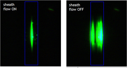
By removing the laser focusing lens and aligning on the stream, a wide vertical area of stream is visible. You an depressurize the sheath air and watch the sheath flow confinement fail, where the beads fill the entire flow cell. A dramatic example of the importance of sheath flow!
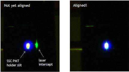
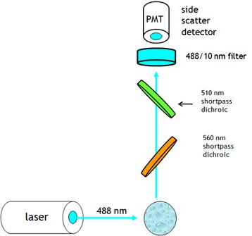
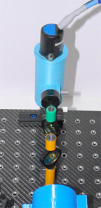
With beads running, we can install and align the detectors. Mount the side scatter detector with attached PMT on the rail at the back of the instrument. Then mount the dichroic mirrors in their magnetic holders on the baseplate. Remove the PMT, and insert an LED backlight into the holder, so that the LED array is facing the flow cell.
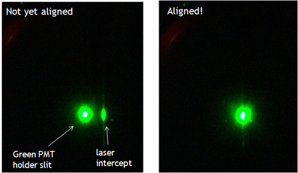
Observe the camera image, and look for the LED glow visible through the side scatter slit. It will probably be off-alignment from the bead spot. Slide the PMT holder left and right until it aligns horizontally, and adjust the laser steering optic until the bead spot and the side scatter slit line up vertically.
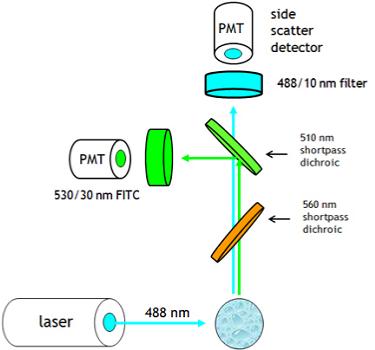
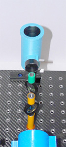
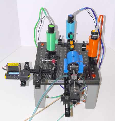
Next, install the FITC detector (green markings) on the breadboard, to the left and forward of the side scatter detector. Remove the PMT, and install a backlight in the holder. Look for the green LED spot on the camera image, and adjust the dichroic and position of the PMT holder until the LED spot and the bead spot line up horizontally. Adjust the knobs on the dichroic holder to adjust vertically. Make sure the two spots superimpose, then clamp everything down, remove the backlight and reinsert the PMT.
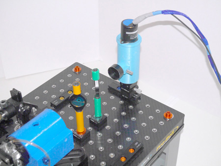
This is the optical layout so far.
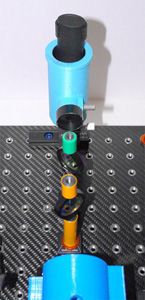
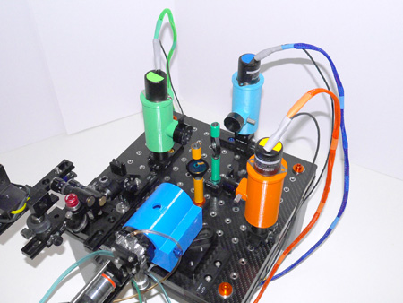
Next, install the PE detector (red markings) on the breadboard, to the right and forward of the side scatter detector. Remove the PMT, and install a backlight in the holder. Look for the orange LED spot on the camera image, and adjust the dichroic and position of the PMT holder until the LED spot and the bead spot line up horizontally. Adjust the knobs on the dichroic holder to adjust vertically. Make sure the two spots superimpose, then clamp everything down, remove the backlight and reinsert the PMT.
To continue installation, click here.
To go to the main page, click here.
This is the optical layout so far.