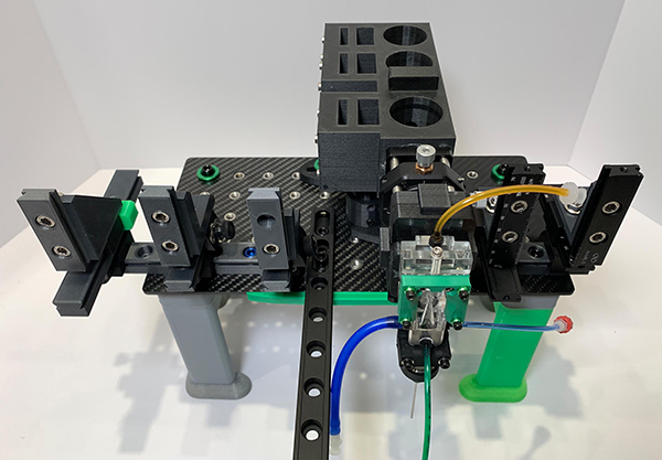
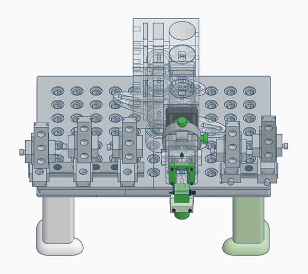
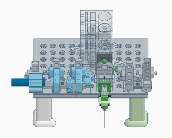
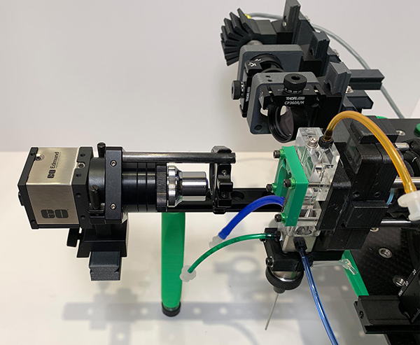
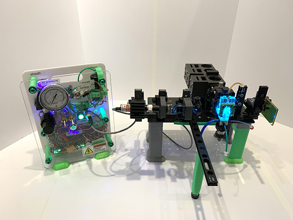
The Make Your Own Flow Cytometer is intended to be assembled by students under the guidance of an instructor. It starts with an empty carbon fiber or 3D printed breadboard, and the various components of the cytometer (laser, optics, flow cell, etc.) are added in sequence. The instrument is then aligned and connected to its electronics an computer. Fluorescent microspheres are usually used as analysis material, although it can also run cells. By running microspheres, we can visualize the stream on the camera.
The current system evolved from an earlier version, and makes considerable use of 3D printed ocmponents. The system is constantly being improved. Feedback is very welcome!
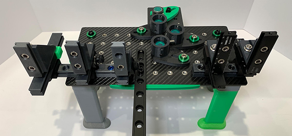
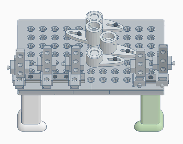
Here is the breadboard, 3D printed in multiple layers using carbon fiber ASA filament. It is supported on 3D printed ASA plastic legs, and already has some optical rails mounted on it to facilitate assembly of the other components.
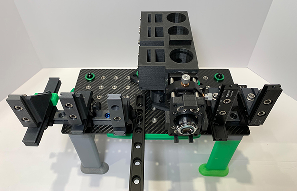
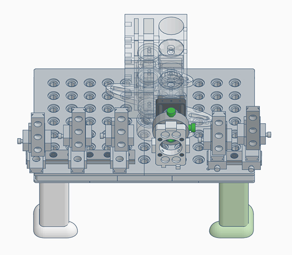
First, we mount the optics shell, whch will hold the flow cell, the bandpass filters and dichroics and the PMTs. All scatter and fluorescence emission signals will pass through this shell.
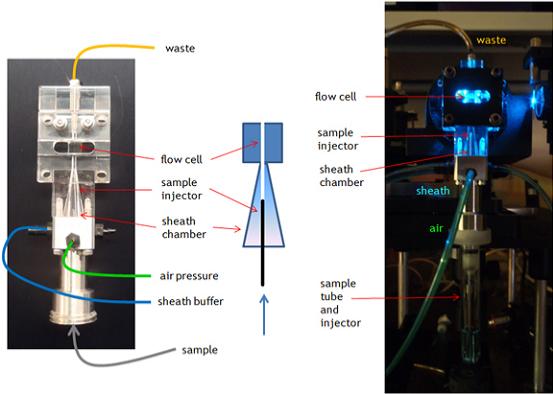
Next, we mount the flow cell. Like the earlier version, it is a standard BD Biosciences designed quartz cuvette flow cell with ports for sheath, sample air and waste.
The flow cell cuvette is mounted in a plastic frame, with sheath provided through a conical reservoir underneath. The SIP tube is inserted into the flow cell, which allows mounting of the sample tube and a port for pressurization of the sample.
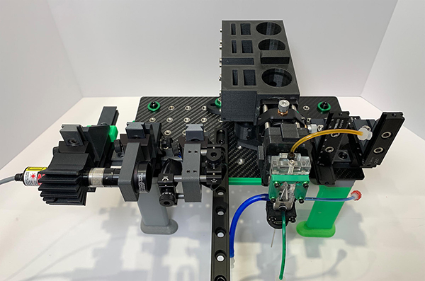
The 488 nm laser, laser focusing optic and beam steering optics are then installed.
The cytometer power and air pressure console is then set up, and the laser connected to power.
The stream camera is installed and aligned to the illuminated flow cell. The camera is then connected to the laptop computer and the flow cell capillary visualized.
The Make Your Own Flow Cytometer